|
Performance Steps
|
|
1. Clear the caliber .50 machine gun.
|
a.
Unlock the bolt latch
release and raise the cover (figure 071-022-0001-1).
|
b.
Pull and lock the bolt to
the rear, leaving the retracting slide
handle to the rear.
|
c.
Inspect the chamber and
T-slot to make sure they hold no
rounds.
|
d.
Place a wooden block inside
the receiver, between the bolt and the
rear of the barrel.
|
e.
Insert the cleaning rod in
the muzzle end of the barrel until you
can see the rod in the receiver.
Remove the cleaning rod.
|
f.
Grasp the retracting slide
handle, press the bolt latch release,
and ease the bolt forward. Close the
cover.
|
|
Figure 071-022-0001-1.
Raising the cover
|
|
2. Disassemble the machine gun.
|
a.
Remove the barrel assembly.
|
(1)
Raise the cover group
(figure 071-022-0001-1).
|
(2)
Grasp the retracting slide
handle with the right hand, palm up.
Pull the bolt to the rear until the
barrel locking spring lug aligns with
the 3/8-inch hole in the right side
plate of the receiver (figure 071-022-0001-2).
|
(3)
Place the smallest loop of
a caliber .50 link between the
trunnion block and the barrel
extension (figure 071-022-0001-2).
This keeps the barrel locking spring
lug aligned with the 3/8-inch hole.
|
(4)
Unscrew the barrel from the
receiver. Be careful not to damage the
threads or barrel locking notches.
|
(5)
Remove the caliber .50 link
to allow the bolt to go forward
slowly. Make sure the bolt group does
not slam forward with the barrel
removed.
|
|
Figure 071-022-0001-2.
Alignment of the lug
|
b.
Remove the backplate
assembly.
|
|
WARNING:
Do not remove
the backplate unless the bolt is in
the forward position. When removing
the backplate, stand to one side of
the weapon to avoid possible injury
from the driving spring rod.
|
(1)
Ensure that the bolt is
forward and the bolt latch release is
unlocked (in the single shot mode)
(figure 071-022-0001-3).
|
|
Figure 071-022-0001-3.
Releasing the bolt latch
|
(2)
Pull the backplate latch
lock straight back while lifting up on
the backplate latch (figure 071-022-0001-4).
|
|
Figure 071-022-0001-4.
Removal of the backplate
|
(3)
Remove the backplate
assembly by lifting straight up.
|
c.
Remove the driving spring
rod assembly (figure 071-022-0001-5).
|
|
Figure 071-022-0001-5.
Removal of the driving spring rod
assembly
|
(1)
Push the rear of the
driving rod assembly forward and to
the left to free it from the side of
the receiver.
|
|
WARNING:
Never try to
charge the machine gun while the
backplate is off and the driving
spring rod assembly is in place. If
the backplate is off and the driving
spring assembly is compressed, the
retaining pin on the driving spring
can slip from its seat in the side
plate. This could cause serious
injury to anyone behind the machine
gun.
|
(2)
Pull the driving spring rod
assembly to the rear and out of the
receiver.
|
d.
Remove the bolt assembly.
|
(1)
Retract the bolt assembly
far enough to the rear to align the
bolt stud with the bolt stud hole in
the right side plate of the receiver
(figure 071-022-0001-6).
|
|
Figure 071-022-0001-6.
Removal of the bolt stud
|
(2)
If you accidentally move
the bolt all the way to the rear, the
bolt latch will engage in the bolt
latch notches in the top of the bolt.
If this occurs, raise the bolt latch
and push the bolt forward to align the
bolt stud with the clearance hole
(figure 071-022-0001-7).
|
|
Figure 071-022-0001-7.
Unlatching the bolt
|
(3)
Remove the bolt stud.
|
(4)
Remove the bolt assembly by
pulling it from the rear of the
receiver (figure 071-022-0001-8).
|
|
Figure 071-022-0001-8.
Removal of the bolt from the receiver
|
(5)
Disassemble the bolt.
|
(a)
Rotate the cartridge
extractor upward and remove it from
the left side of the bolt (figure 071-022-0001-9).
|
|
Figure 071-022-0001-9.
Removal of the cartridge extractor and
bolt
|
(b)
Remove the bolt switch by
lifting it straight up.
|
(c)
Place the cocking lever in
its rearmost position. Press down on
the sear with a swab holder and
release the firing pin spring (figure 071-022-0001-10).
|
|
Figure 071-022-0001-10.
Releasing the firing pin spring
|
(d)
Insert a swab holder
section in the hole at the rear of the
bolt and push out the cocking lever
pin and the cocking lever (figure 071-022-0001-11).
|
|
Figure 071-022-0001-11.
Removal of the cocking lever pin and
cocking lever
|
(e)
Use the thin end of the
cocking lever to rotate the
accelerator stop lock to the center of
the bolt, then pry up the accelerator
stop lock and remove it (figure 071-022-0001-12).
|
|
Figure 071-022-0001-12.
Removal of the accelerator stop lock
|
(f)
Using the thin end of the
cocking lever, press the accelerator
stop from the bolt, turn the bolt
over, and pry the accelerator stop
from bottom of bolt (figure 071-022-0001-13).
|
|
Figure 071-022-0001-13.
Removal of the accelerator stop
|
(g)
Depress the sear and remove
the sear slide, sear, and sear spring
(figure 071-022-0001-14).
|
|
Figure 071-022-0001-14.
Removal of the sear slide, sear, and sear spring
|
(h)
Tip the front end of the
bolt upward and remove the firing pin
extension assembly (figure 071-022-0001-15).
|
|
Figure 071-022-0001-15.
Removal of the firing pin extension
assembly
|
(i)
Remove the firing pin from
the firing pin extension assembly.
|
e.
Remove the barrel buffer
and barrel extension assemblies
(figure 071-022-0001-16).
|
|
Figure 071-022-0001-16.
Removal of the barrel buffer group and
barrel extension group
|
(1)
Insert a pointed instrument
(you can use the pointed end of the M4
cleaning rod) in the hole at the lower
rear corner of the right side plate.
Depress the buffer body lock and, at
the same time, place one hand inside
the receiver and push the barrel
extension and buffer assemblies to the
rear until the buffer accelerator is
near the rear of the receiver body.
|
|
WARNING:
Maintain
thumb pressure on the buffer
accelerator while removing the
barrel buffer and barrel extension
assemblies.
|
(2)
Maintain pressure on the
buffer accelerator with your thumb and
remove the barrel buffer and barrel
extension assemblies from the
receiver. Separate them by pushing
forward on the accelerator tips
(figure 071-022-0001-17).
|
|
Figure 071-022-0001-17.
Separation of the barrel buffer and
barrel extension assemblies.
|
(3)
Disassemble the barrel
buffer assembly.
|
(a)
Remove the buffer assembly
by pushing it out the rear of the body
of the barrel buffer (figure 071-022-0001-18).
|
|
Figure 071-022-0001-18.
Removal of the barrel buffer assembly
|
(b)
Using a swab holder, drive
the accelerator pin assembly from the
barrel buffer body group.
|
(c)
Remove the buffer
accelerator.
|
(4)
Disassemble barrel
extension assembly.
|
(a)
Using the pointed end of
the M4 cleaning rod, remove breech
lock pin assembly (figure 071-022-0001-19).
|
|
Figure 071-022-0001-19.
Removal of
the breech lock pin assembly and
breech lock
|
(b)
Remove breech lock.
|
f.
Disassemble receiver
assembly.
|
(1)
Remove the front cartridge
stop and rear cartridge stop assembly
(figure 071-022-0001-20).
|
|
Figure 071-022-0001-20.
Removal of the cartridge stop
assemblies
|
(2)
Press down on belt holding
pawl assembly to prevent loss of
springs, and remove the belt holding
pawl pin. Remove belt holding pawl
assembly and springs (figure 071-022-0001-21).
|
|
Figure 071-022-0001-21.
Removal of the belt holding pawl pin,
assembly, and springs
|
(3)
Raise the loop of the
trigger lever pin and rotate it into a
vertical position. Reach inside the
receiver, grasp the trigger lever, and
remove the trigger pin assembly and
trigger lever (figure 071-022-0001-22).
|
|
Figure 071-022-0001-22.
Removal of the trigger lever pin
assembly and trigger lever
|
|
3. Clean the .50 caliber machine gun and components.
|
a.
Barrel assembly.
|
(1)
Clean the bore. Screw the
bore brush into the cleaning rod, dip
the bore brush in RBC, and push the
cleaning rod through the chamber end
of barrel. Unscrew the bore brush from
the cleaning rod. Repeat the process
until clean.
|
(2)
Clean the chamber. Screw
the chamber brush into the cleaning
rod, dip the chamber brush in RBC, and
clean the chamber using a clockwise
twisting motion.
|
(3)
Insert a cleaning swab in
the cleaning rod and swab out the bore
from the chamber end and back. Repeat
until a swab comes out clean.
|
(4)
Wipe outside surfaces of
barrel with carbon removing compound.
|
(5)
Remove all traces of RBC
before lubricating.
|
|
Note. Do not submerge the backplate assembly in any fluid.
|
b.
Backplate assembly. Use
only clean wiping rags to remove
foreign matter from backplate.
|
c.
Bolt assembly. Clean all
parts of bolt assembly with a cleaning
swab saturated with carbon removing
compound. Clean the face of the bolt
with a cleaning swab soaked in RBC.
|
d.
Clean barrel buffer
assembly, barrel extension assembly,
and receiver assembly with a cleaning
swab saturated with carbon removing
compound. Wipe all parts dry with
clean wiping rags.
|
e.
Clean components.
|
(1)
T&E mechanism.
Remove foreign matter with a
clean dry wiping rag.
Use a small arms cleaning brush
to clean numbers on the scale.
|
(2)
Clean M3 tripod, MK64 gun
cradle mount, and pintle with a
cleaning swab saturated with carbon
removing compound.
Wipe all parts dry with clean
wiping rags.
|
f.
Ammunition. Remove foreign matter with a clean dry wiping rag.
|
|
4. Inspect for serviceability.
|
a.
Barrel assembly.
|
(1)
Check barrel locking
notches for wear.
|
(2)
Check the bore for bulges,
missing bands, and large pits.
|
b.
Backplate assembly.
|
(1)
Check guides for burrs and
bends.
|
(2)
Check backplate latch and
backplate lock for proper functioning.
|
(3)
Make sure locking pins are
in place.
|
(4)
Check trigger and bolt
latch release for proper functioning.
|
(5)
Make sure handle grips do
not move freely and are not cracked.
|
c.
Driving rod assembly.
|
(1)
Check for flat spots on
springs.
|
(2)
Make sure springs operate
freely and rod and pin are not bent.
|
d.
Bolt assembly.
|
(1)
Check movement of cartridge
extractor in bolt; it should raise and
lower without binding. Check movement of cartridge ejector.
|
(2)
Check bolt switch, cocking
lever pin, cocking lever, accelerator
stop lock, accelerator stop, and sear
slide for cracks, bends, and burrs.
|
(3)
Inspect sear for cracks and
burrs.
Inspect sear notch for wear,
chips, and burrs.
Inspect sear spring for breaks
and lack of tension.
|
(4)
Inspect firing pin for
cracks and chipped or sharp tip.
Tip should be smooth and well
rounded.
|
(5)
Check firing pin extension
for cracks, burrs, and free movement
in bolt.
|
(6)
Make sure bolt is free of
burrs and cracks and firing pin hole
is not visually out of round.
|
e.
Barrel buffer assembly.
|
(1)
Inspect buffer body lock
for tension, staking, and retention in
barrel buffer body.
|
(2)
Inspect buffer accelerator
for broken claws or chipped tips.
|
(3)
Inspect accelerator pin
assembly for broken or missing spring.
|
(4)
Inspect buffer spring for
cracks or breaks.
|
(5)
Inspect breech lock
depressors.
They must have slight vertical
(up and down) movement but should have
no lateral (side to side) movement.
|
f.
Barrel extension assembly.
|
(1)
Make sure barrel extension
assembly is not bent and the bolt
guideways are smooth and free of
burrs.
|
(2)
Inspect threads of barrel
extension assembly for damage.
|
(3)
Make sure barrel locking
spring is staked and fully seated in
its groove.
Also, make sure the locking end
of the spring has good tension and the
lug is not damaged.
|
(4)
Check breechblock for
smooth movement in guideways of barrel
extension assembly.
|
g.
Receiver and cover
assembly.
|
(1)
Inspect belt holding pawl
brackets for looseness, bends, and
cracks.
|
(2)
Inspect side plates for
bends that would affect movement of
any internal parts.
|
(3)
Check for cracks and burrs
at backplate grooves.
|
(4)
Check operation of rear
sight.
Make sure windage and elevation
screws function properly, leaf
assembly has good spring tension, and
sight assembly is secured tightly to
receiver.
|
(5)
Make sure bolt stop is
present and in good condition.
|
(6)
Make sure trigger lever
moves freely.
|
(7)
Make sure trigger lever pin
locks in place.
|
(8)
Make sure cotter pin is in
place on extractor switch.
|
(9)
Check retracting slide
assembly for visible damage.
Check retracting slide handles
for smooth movement.
Make sure cotter pins are
present and in good condition, and
safety wire is in place and properly
laced.
|
h.
Inspect components.
|
(1)
T&E mechanism.
|
(a)
Inspect hand wheels and
threads for burrs and rust.
Check hand wheels for smooth
operation.
|
(b)
Make sure traversing slide
lock lever has spring action.
Make sure elevating mechanism
sleeve fits on traversing bar and
clamps firmly.
|
(c)
Check traversing and
elevating scales for legibility.
|
(d)
Inspect quick release pin
and chain for burrs and rust.
Check quick release pin for
presence of spring loaded balls.
|
(2)
M3 tripod.
|
(a)
Check for completeness of
tripod.
Make sure all nuts and bolts
are tightly secured.
|
(b)
Check for visible cracks on
legs and tripod head.
|
(c)
Check for missing, broken,
or inoperative sleeve lock latch.
|
(d)
Check pintle lock assembly.
Check surfaces of pintle, bolt,
and nut for burrs and rust.
Make sure cotter pin is present
and in good condition.
|
(e)
Check locking action of
front leg clamping assembly.
|
(f)
Check that rear legs lock
in the open position.
Make sure sleeve latch notch
and right leg slide notch engage
completely. Make sure latch spring has good tension.
|
(g)
Check telescoping,
indexing, and locking action of rear
legs and front leg clamping assembly.
|
(3)
MK64 gun cradle mount.
|
(a)
Check for missing or
damaged parts.
|
(b)
Check for rust, cracks, and
burrs.
|
(c)
Check pintle lock assembly.
Check surfaces of pintle, bolt,
and nut for burrs and rust.
Make sure cotter pin is present
and in good condition.
|
i.
Inspect ammunition.
Check for damage or corroded
rounds.
|
|
5. Lubricate the .50 caliber machine gun.
|
a.
Remove all traces of RBC or
carbon removing compound.
|
|
CAUTION:
Do not mix
lubricants on the same weapon.
The weapon must be thoroughly
cleaned with dry cleaning solvent
during change from one lubricant to
another.
|
b.
Lubricate exterior of
backplate with a light coat of oil.
Do not lubricate interior of
backplate.
|
c.
Lubricate all other parts
with a light coat of LSA or CLP (at
temperatures above 0 degrees
Fahrenheit) or LAW (at temperatures
below 0 degrees Fahrenheit).
|
|
6. Assemble the .50 caliber machine gun.
|
a.
Assemble the trigger lever
(Figure 071-022-0001-23).
|
|
Figure 071-022-0001-23.
Assembly of the trigger lever
|
(1)
Place the trigger lever bar
in the receiver directly under the
timing nut so the hole in the trigger
lever bar is aligned with the mounting
hole in the receiver.
|
(2)
Insert trigger lever pin
assembly (loop end vertical) in the
assembly hole on left side of
receiver.
Match key on trigger lever pin
with keyway in side plate of receiver
and install the pin completely.
|
(3)
Rotate trigger pin lever
assembly 90 degrees and lock in place.
Fold the loop end down.
|
b.
Assemble receiver group.
|
(1)
Determine the direction of
feed.
Figure 071-022-0001-24
shows left-hand feed.
Place the right-hand rear
cartridge stop assembly and front
cartridge stop on the belt holding
pawl bracket.
|
|
Figure 071-022-0001-24.
Installation of the rear cartridge
stop assembly and front cartridge stop
|
(2)
Install belt holding pawl
pin with hooked end to rear.
|
(3)
Seat belt holding pawl
springs in place on the belt holding
pawl bracket.
|
(4)
Place belt holding pawl
assembly on the springs.
Compress springs and insert
belt holding pawl pin (figure 071-022-0001-25).
|
|
Figure 071-022-0001-25.
Installation of the belt holding pawl
assembly
|
c.
Assemble barrel extension
(figure 071-022-0001-26).
|
|
Figure 071-022-0001-26.
Assembly of the barrel extension assembly
|
(1)
Install breechblock lock
with beveled edge up and to the front
of barrel extension assembly.
|
(2)
Install breech lock pin
assembly in barrel extension.
Make sure both ends of breech
lock pin assembly are flush with sides
of barrel extension assembly.
|
d.
Assemble barrel buffer
assembly.
|
(1)
Place buffer accelerator
(tips up) into barrel buffer body,
align mounting holes, and install
buffer pin assembly.
Ensure both ends of barrel
buffer pin assembly are flush with
sides of barrel buffer body (figure 071-022-0001-27).
|
|
Figure 071-022-0001-27. Assembly
of the barrel buffer assembly
|
(2)
Align key on barrel buffer
assembly with key slot in barrel
buffer body and slide barrel buffer
assembly into barrel buffer body.
|
(3)
Hold the barrel buffer
assembly with the buffer accelerator
up and engage the notch on the shank
of the barrel extension assembly with
the cross groove in the piston rod of
the barrel assembly (figure 071-022-0001-28).
|
|
Figure 071-022-0001-28.
Attachment of the barrel buffer and barrel extension assemblies
|
(4)
Align breech lock
depressors in grooves of barrel
extension assembly and push barrel
buffer assembly forward.
|
(5)
Install barrel buffer
assembly and barrel extension assembly
in receiver (figure 071-022-0001-29).
|
|
Figure 071-022-0001-29.
Installation of the barrel buffer and barrel extension assemblies
|
e.
Assemble bolt assembly.
|
(1)
Attach firing pin to firing
pin extension assembly (figure 071-022-0001-30).
|
|
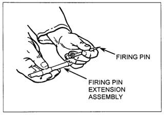
Figure 071-022-0001-30.
Attachment of the firing pin to the firing pin extension assembly
|
(2)
Insert firing pin extension
assembly into bolt with notch of
firing pin extension assembly down
(Figure 071-022-0001-31).
|
|
Figure 071-022-0001-31.
Installation of the firing pin
extension assembly
|
(3)
Slide firing pin extension
assembly forward so tip of firing pin
protrudes from face of bolt.
|
(4)
Place sear spring in recess
on bolt.
Slide sear down into vertical
grooves at rear of bolt with
wedge-shaped lug pointed outward and
upward (figure 071-022-0001-32).
|
|
Figure 071-022-0001-32.
Installation of the sear side
|
(5)
Compress sear spring by
pressing down on the sear.
Install sear slide from left
side of bolt in grooves of bolt with
"V" notch down.
|
|
Note. Make sure
the pin end of the accelerator is
installed behind the firing pin
spring, not through a coil.
|
(6)
Insert pin end of
accelerator stop through bottom of
bolt (figure 071-022-0001-33).
|
|
Figure 071-022-0001-33.
Attachment of the accelerator stop
|
|
Note. Base end of
accelerator stop should be installed
with long end forward so beveled edges
match.
|
(7)
Turn bolt over.
Place forked end of accelerator
stop lock on notched end of
accelerator stop.
|
(8)
Using the wedge-shaped end
of the cocking lever, press down on
the flat end of the accelerator stop
lock, and move the cocking lever into
the groove on the left side of the
bolt (figure 071-022-0001-34).
|
|
Figure 071-022-0001-34.
Attachment of the accelerator stop
lock
|
(9)
Insert cocking lever, with
rounded nose on lower end of lever to
rear, into slot in top of bolt (figure
071-022-0001-35).
|
|
Figure 071-022-0001-35.
Attachment of the cocking lever
|
(10)
Align the hole in the
cocking lever with the holes in the
bolt.
Insert the cocking lever pin
from the left side.
|
(11)
Push the cocking lever
forward to charge the firing pin.
Return the cocking lever to the
rearward position.
|
|
WARNING:
Do not try to
release the firing pin with the
cocking lever forward.
The cocking lever could
spring back forcibly and cause
serious injury.
|
(12)
Test firing pin release.
Trip the firing pin by
depressing the top of the sear with a
section of a swab-holder.
If doing so makes a sharp
metallic sound, the firing pin spring
is in good condition (figure 071-022-0001-36).
|
|
Figure 071-022-0001-36. Testing the firing pin release
|
(13)
Place cocking lever in forward
position.
Determine the direction of feed
before installing the bolt switch.
|
(14)
Place bolt switch in
position so the feed groove is
continuous for feed direction
indicated (figure 071-022-0001-37).
|
|
Figure 071-022-0001-37.
Setting the bolt switch
|
(15)
Hold cartridge extractor in
vertical position and insert shank end
of cartridge extractor into left side
of bolt.
Make sure cartridge extractor
fits into bolt as far as possible.
|
(16)
Rotate cartridge extractor
downward to full horizontal position.
Check that flange on bottom of
cartridge extractor has engaged
shoulder on bolt.
|
(17)
Ensure cocking lever is
forward.
|
(18)
Push bolt assembly forward
into receiver until bolt latch engages
notches in top of bolt assembly
(figure 071-022-0001-38).
|
|
Figure 071-022-0001-38.
Installation of the bolt assembly
|
(19)
If you cannot install the
bolt this way, remove the barrel
extension and buffer assembly from the
receiver.
Install the bolt assembly into
the barrel extension and buffer
assembly, then install them in the
receiver (figure 071-022-0001-39).
|
|

Figure 071-022-0001-39.
Installation of the bolt assembly
within the barrel extension and buffer assembly
|
(20)
Raise bolt latch and push
bolt assembly into the receiver.
|
(21)
Align holes in bolt
assembly with stud assembly hole in
receiver and install bolt stud in hole
in bolt assembly.
Place bolt in forward position
(figure 071-022-0001-40).
|
|
Figure 071-022-0001-40. Installation of the bolt assembly
|
f.
Assemble driving spring rod
assembly (figure 071-022-0001-41).
Install the driving spring rod
assembly in the upper right corner of
the bolt.
Push forward and to the right
until the driving spring rod assembly
engages in the hole in the side plate
of the receiver-not in the groove
for the backplate.
|
|
Figure 071-022-0001-41. Installation of the driving spring
rod assembly
|
g.
Install backplate assembly
(figure 071-022-0001-42).
|
|
Figure 071-022-0001-42.
Installation of the backplate assembly
|
(1)
Align backplate assembly
with receiver grooves.
Pull backplate latch lock while
lifting up on backplate latch.
Lower backplate assembly down
until engaged in receiver.
|
(2)
Test proper locking by
pulling up on backplate assembly.
|
h.
Assemble barrel assembly.
|
(1)
Retract bolt far enough for
barrel locking spring lug to center in
barrel locking spring hole on right
side of receiver.
|
(2)
Place the smallest loop of
a caliber .50 link between the
trunnion block and the barrel
extension.
This holds the barrel locking
spring lug aligned with the 3/8-inch
hole.
|
(3)
Install and screw barrel
assembly completely into receiver.
Unscrew barrel assembly two
clicks and check headspace.
|
|
7. Perform a function check to make sure weapon is
assembled correctly.
|
a.
Place the weapon in the
single-shot mode.
|
b.
Open the cover and pull the
retracting slide handle to the rear.
Bolt should lock to rear in
single-shot mode.
|
c.
Hold the retracting slide
handle to the rear; depress bolt latch
release and ease the bolt forward.
|
d.
Press trigger; weapon
should fire.
|
e.
Place the weapon in the
automatic-fire mode.
|
f.
Pull the retracting slide
handle to the rear and hold.
Bolt should not lock to rear in
automatic-fire mode.
|
g.
Release pressure on the
retracting slide handle and ease the
bolt forward.
|
h.
Press trigger; weapon
should fire.
|