Quadrant Sight
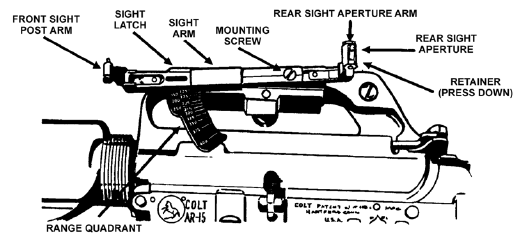
Assembly. The quadrant sight assembly, which
attaches to the left side of the rifle’s carrying handle, enables the
grenadier to adjust for elevation and windage. This assembly consists of the
sight, mounting screw, sight latch, rear sight aperture, sight aperture arm,
front sight post, and sight post arm.

Clamp, Bracket
Assembly, and Mounting Screw. The clamp and the
bracket assembly hold the quadrant sight on the rifle’s carrying handle. The
mounting screw inserts through the right side of the clamp and into the
bracket assembly.
-
Sight Arm and Range
Quadrant. The sight arm mounts both the sight
aperture arm (which holds the rear sight aperture) and the sight post arm
(which holds the front sight post). This procedure allows the sight to
pivot on the range quadrant to the desired range setting. The range
quadrant is graduated in 25-meter increments from 50 to 400 meters.
Applying rearward pressure on the sight latch releases the quadrant sight
arm so it can move along the range quadrant. Centering the number in the
rear sight aperture selects the desired range. Releasing the sight latch
locks the sight in position.
-
Front Sight Post.
The front sight post mounts on the sight post arm by means of a pivot
bracket. To prevent damage to the sights, keep the bracket closed when the
sights are not in use. Use the sight post as follows to make minor
adjustments in elevation when zeroing the launcher:
-
To decrease elevation,
turn the elevation adjustment screw on the sight post clockwise; to
increase elevation, turn it counterclockwise.
-
To move the impact of the
projectile 5 meters at a range of 200 meters, turn the elevation
adjustment screw one full turn–360 degrees. To move the impact of the
projectile 2.5 meters at a range of 200 meters, turn the elevation
adjustment screw one half turn–180 degrees.
-
Rear Sight Aperture.
The rear sight aperture is on the sight aperture arm, which is attached to
the rear portion of the quadrant sight arm. Use the rear sight aperture as
follows to make minor adjustments in deflection (windage) when zeroing the
launcher:
-
To move the impact to the
left, press the rear sight aperture retainer down and move the rear
sight aperture away from the barrel; to move to the right, move it
toward the barrel.
-
To move the impact of the
projectile 1.5 meters at a range of 200 meters, move the rear sight
aperture one notch.
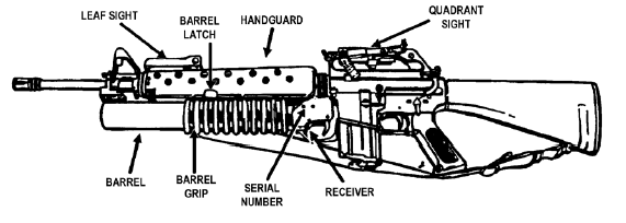
Receiver Assembly and
Serial Number. The receiver assembly houses the
firing mechanism and ejection system and supports the barrel assembly. On
the left side of the receiver assembly is the launcher’s serial number.
Barrel Assembly.
The barrel assembly holds the cartridges ready for firing and directs the
projectile
Barrel Latch.
On the left side of the barrel is a latch that locks the barrel and receiver
together. To open the barrel, depress the barrel latch and slide the barrel
forward.
Leaf Sight Assembly.
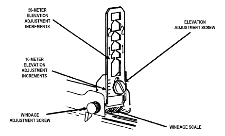
The leaf sight assembly is attached to the top of
the handguard. The leaf sight assembly consists of the sight, its base and
mount, an elevation adjustment screw, and a windage adjustment screw.
Elevation and windage scales are marked on the mount. The folding,
adjustable, open ladder design of the sight permits rapid firing without
sight manipulation. The front sight post of the M16-series rifle serves as
the front aiming post for the M203 leaf sight.

-
Sight Base.
Two mounting screws permanently attach the sight base to the rifle
handguard. When the sight is down or not in use, the base protects it from
damage.
-
Sight Mount and
Sight. The grenadier uses the sight mount, which
is attached to the sight base, to raise or lower the sight. Though the
range is not marked on the sight in meters, the sight is graduated in
50-meter increments from 50 to 250 meters, which are marked with a “1” at
100 meters and a “2” at 200 meters.
-
Elevation
Adjustment Screw and Elevation Scale. The screw
attaches the sight to its mount. When the screw is loosened, the sight can
be moved up or down to make minor adjustments in elevation during the
zeroing procedure. The rim of a 40-mm cartridge case is useful for turning
the screw. Raising the sight increases the range; lowering the sight
decreases the range. The elevation scale consists of five lines spaced
equally on the sight. The index line is to the left of the sight. Moving
the sight one increment moves the impact of the projectile 10 meters in
elevation at a range of 200 meters.
-
Windage Screw and
Windage Scale. The knob on the left end of the
windage screw is used to make minor deflection adjustments during the
zeroing procedure. The scale has a zero line in its center and two lines
spaced equally on each side of the zero line. At a range of 200 meters,
turning the knob on the windage scale one increment to the left moves the
impact of the projectile 1.5 meters to the right.
Trigger Guard.
The trigger guard protects the trigger. Depressing the rear portion of the
trigger guard rotates it down and away from the magazine well of the rifle,
which allows the weapon to be fired while the firer is wearing gloves or
mittens
Safety.
The safety is inside the trigger guard, just in front of the trigger. For
the launcher to fire, the safety must be forward. When the safety is
rearward, the launcher is on SAFE. The safety is manually adjusted. |


