|
Performance Steps
|
|
1. Clear the MK19.
|
a.
Place the safe/fire switch
in the SAFE (S) position. Ensure the
bolt is forward.
|
b.
Open the top cover and
inspect the feed tray and extractors
on the bolt face to ensure that no
round is in the pickup position.
|
c.
Unlock and pull charger
handle 2 to 3 inches to the rear;
inspect the face of the bolt and the
chamber for ammunition.
|
d.
Return the bolt to the
forward position and rotate the
charger handle to the locked position.
|
|
2. Disassemble the MK19.
|
a.
Remove the feed throat
assembly (figure 071-030-0001-1).
Squeeze the two sets of grip pins
together and pull them straight out.
|
b.
Remove the bolt and
backplate assembly.
|
|
Figure 071-030-0001-1.
Removal of feed throat assembly
|
|
WARNING:
Make sure the
bolt is in the forward position
before you remove the backplate pin
assembly. Failure to observe this
warning will result in injury.
|
(1)
Place the safe/fire switch
on FIRE (F).
|
(2)
Open the top cover.
|
(3)
Using the rim of a spent
cartridge, pull the backplate pin
straight out (figure 071-030-0001-2).
|
|
Figure 071-030-0001-2.
Removal of backplate pin
|
(4)
Lift up slightly on the
backplate assembly. Slowly pull the
bolt and backplate assembly out of the
receiver.
|
(5)
Support the bolt with one
hand and maintain a control grip with
the other hand. Lift the bolt up
slightly and remove it (figure 071-030-0001-3).
|
|
Figure 071-030-0001-3.
Removal of bolt and backplate assembly
|
c.
Remove the primary drive
lever and vertical cam assembly.
|
|
CAUTION:
Do not rest the
vertical cam assembly on its chromed
surface.
|
(1)
Reach under the top of the
receiver to locate the drive lever
lock on the vertical cam assembly and
slide the lock rearward about 1/4 inch
(figure 071-030-0001-4).
|
|
Figure 071-030-0001-4.
Primary drive lever and vertical cam
assembly
|
(2)
Press down on the primary
drive lever’s pivot post. This
releases the primary drive lever and
vertical cam assembly (figure 071-030-0001-5).
|
|
Figure 071-030-0001-5. Removal of the primary drive lever
and vertical cam assembly
|
(3)
Pull out the cam (to the
rear) and the lever from the receiver.
|
d.
Remove secondary drive
lever.
|
(1)
Push down on the pivot post
from the outside top cover. This
releases the secondary drive lever
(figure 071-030-0001-6).
|
|
Figure 071-030-0001-6.
Removal of the secondary drive lever
|
(2)
Lift out the secondary
drive lever from the top cover (figure 071-030-0001‑7).
|
|
Figure 071-030-0001-7.
Secondary drive lever.
|
e.
Remove the feed slide
assembly (Figure 071-030-0001-8).
|
|
Figure 071-030-0001-8.
Removal of the feed slide assembly.
|
(1)
Pivot the tray that holds
the feed slide assembly out of the top
cover.
|
(2)
Move the feed slide
assembly to line up the tabs with the
slots in the tray.
|
(3)
Lift upward on the feed
slide assembly.
|
f.
Remove the top cover
assembly and feed tray (figure 071-030-0001-9).
|
|
Figure 071-030-0001-9.
Removal of the top cover assembly and
feed tray
|
|
CAUTION:
Using your
fingers only, not pliers, remove the
top cover pins. Forcing the pin
could break the small cross pin on
the rod.
|
|
Note. The feed tray must be down for you to remove the top
cover pins.
|
(1)
Hold the top cover straight
up to align the end of the cross pin.
|
(2)
Pull straight out on the
pins.
|
(3)
Lift off the top cover.
|
(4)
Lift the tray out of the
feeder.
|
g.
Remove the alignment guide
assembly (figure 071-030-0001-10).
|
|
Figure 071-030-0001-10.
Removal of the alignment guide assembly
|
(1)
Depress the flat leaf
spring by using a cartridge link
toggle (male end) or a small tool.
|
(2)
Slide the alignment guide
toward the feeder mouth.
|
(3)
Pull rearward on the
alignment guide and lift it out.
|
h.
Remove the ogive plunger by
pulling it out (figure 071-030-0001-11).
|
|
Figure 071-030-0001-11.
Removal of the ogive plunger
|
i.
Remove the round
positioning block (figure 071-030-0001-12).
|
|
Figure 071-030-0001-12.
Removal of the round positioning block
|
(1)
Grasp the two control grips
with both hands and lift up slightly
to disengage the backplate from the
locking lugs in the receiver.
|
(2)
Pull the round positioning
block toward the muzzle end of gun.
|
j.
Remove the charger
assemblies (both sides) (figure 071-030-0001-13).
|
|
Figure 071-030-0001-13.
Removal of the charger assembly
|
(1)
Rotate the charger handle
up.
|
(2)
Using either your fingers
or a spent case, pry out on the lip of
the lock plunger.
|
(3)
Lift up on the lock plunger
to retract it; slide the charger
assembly all the way to the rear.
|
(4)
Pull the charger assembly
away from the receiver.
|
k.
Remove the receiver sear
assembly (figure 071-030-0001-14).
|
|
Figure 071-030-0001-14.
Removal of the receiver sear assembly
|
(1)
Turn the receiver on its
top. Put the safe/fire switch in FIRE
(F) position.
|
(2)
Lift up slightly on the
lock pin with your fingers, using a
cartridge link.
|
(3)
Squeeze the receiver sear
(underneath the safety) and
simultaneously rotate the sear housing
assembly approximately 15 degrees in
either direction.
|
(4)
Press down on the sear
housing assembly and rotate the
assembly until it stops (90 degrees
from its original position).
|
(5)
Press the receiver sear and
safety together while you put
safe/fire switch on safe (S). This
locks the sear in the down position
and keeps you from accidentally losing
the sear spring.
|
(6)
Lift out the sear housing
assembly.
|
|
3. Clean the parts of the MK19.
|
|
Note. Do not reverse the direction of the bore brush while it
is in the bore.
|
a.
Clean the receiver assembly
(figure 071-030-0001-15).
|
|
Figure 071-030-0001-15.
Receiver assembly
|
(1)
Apply solvent to a rag or
brush. Wipe or brush dirt away from
all parts, especially the interior of
the receiver housing, receiver rails,
and feeder.
|
(2)
Swab out the bore and
chamber, using a bore brush and RBC.
|
(3)
Wipe all parts dry.
|
b.
Clean the receiver sear
assembly (figure 071-030-0001-14).
|
(1)
Use only cleaning solvent
on a rag or brush.
|
(2)
Wipe or brush away dirt.
|
(3)
Wipe dry.
|
|
WARNING:
Never immerse
the sear housing assembly in
solvent. Solvent may dilute the
lubricant inside the sear housing.
|
c.
Clean the alignment guide
assembly, ogive plunger, round
positioning block, and secondary drive
lever; wipe or brush off dirt and dry.
|
|
WARNING:
Never immerse
the ogive plunger assembly in
solvent.
|
d.
Clean the charger
assemblies.
|
(1)
Apply cleaning solvent to a
rag or brush, and wipe or brush off
dirt.
|
(2)
Wipe dry.
|
e.
Clean the vertical cam
assembly, primary drive lever, feed
slide assembly, and feed tray.
|
(1)
Soak in cleaning solvent.
|
(2)
Wipe or brush off dirt.
|
(3)
Wipe dry.
|
f.
Clean the top cover
assembly.
|
(1)
Apply cleaning solvent to a
rag or brush and wipe or brush off
dirt from all parts.
|
(2)
Wipe all surfaces dry.
|
g.
Clean the bolt and
backplate assembly.
|
(1)
Apply cleaning solvent to
rag or brush and wipe or brush off
dirt from all parts.
|
(2)
Wipe all surfaces dry.
|
|
4. Clean the components.
|
a.
Clean the T&E
mechanism.
|
(1)
Remove foreign matter with
a clean, dry wiping rag.
|
(2)
Use small arms cleaning
brush to clean the numbers on the
scale.
|
b.
Clean the M3 tripod, MK64
gun cradle mount, and pintle.
|
(1)
Use a cleaning swab
saturated with carbon removing
compound to remove dirt.
|
(2)
Wipe all parts dry with
clean wiping rags.
|
|
5. Clean ammunition. Remove foreign matter with a
clean, dry wiping rag.
|
|
6. Inspect all MK19 parts for serviceability.
|
a.
Receiver assembly.
|
(1)
Check the receiver housing
for cracks and rust.
|
(2)
Check the receiver rails
for burrs and cracked welds.
|
(3)
Check the feeder pawls for
burrs and lack of spring action. Check
the pins for retention.
|
(4)
Check the barrel for carbon
buildup and pitting in the bore and
chamber.
|
(5)
Check the flash suppressor
for dents, cracks, and erosion. Make
sure minimal movement is maintained.
|
(6)
Check the rear sight for
rust, binding, and broken or bent
parts.
|
b.
Receiver sear assembly.
|
(1)
Check for burrs on all
parts.
|
(2)
Closely inspect the rear
shoulder for burrs.
|
c.
Alignment guide assembly.
|
(1)
Check the alignment guide
spring for deformity, cracks, and
looseness.
|
(2)
Check the pin for breaks
and cracks.
|
d.
Ogive plunger assembly and
round positioning block.
|
(1)
Check the ogive plunger
head for burrs and broken parts.
|
(2)
Check the round positioning
block for weak spring action and loose
or broken parts.
|
e.
Charger assembly (left and
right).
|
(1)
Check the grooved edges for
burrs and bends.
|
(2)
Check the latches for
spring action on detects.
|
(3)
Check the entire charger
assembly for cracks, burrs, bends, and
chips.
|
f.
Vertical cam assembly and
primary drive lever.
|
(1)
Check the vertical cam
assembly for bends, burrs, pits,
scratches, and aluminum buildup on
chromed surface (mirror-like surface).
|
(2)
Check the drive lever lock
for looseness or binding.
|
(3)
Check the primary drive
lever for burrs, especially around the
pivot posts.
|
g.
Secondary drive lever.
|
(1)
Check for missing retaining
ring from the pivot post.
|
(2)
Check the pivot post and
forked end for burrs.
|
h.
Feed slide assembly and
feed tray.
|
(1)
Check the feed pawls and
feed tray for burrs and binding.
|
(2)
Check the guide rails for
burrs.
|
i.
Top cover assembly.
|
(1)
Check the top cover housing
for cracks and rust.
|
(2)
Check the latch for
binding, looseness, and breaks.
|
j.
Bolt and backplate
assembly.
|
(1)
Check the cocking lever for
chips, burrs, and breaks.
|
(2)
Check the guide rods for
binding and bends.
|
(3)
Check the recoil spring for
weak action. Position the bolt end
against a hard, flat surface and push
up and down on backplate assembly.
|
(4)
Check the backplate pin for
missing retaining spring.
|
(5)
Check for missing, loose or
broken safety wire.
|
k.
Report any deficiencies to
supervisor.
|
|
7. Inspect all components for serviceability.
|
a.
T&E mechanism.
|
(1)
Inspect the hand wheels for
smooth operation and rust. Check the
threads for burrs and rust.
|
(2)
Check the traversing slide
lock for spring action. Make sure the
elevating mechanism sleeve fits on the
traversing bar and clamps firmly.
|
(3)
Check the traversing and
elevating scales for legibility.
|
(4)
Inspect the quick release
pin and chain for burrs and rust;
check for missing spring-loaded balls.
|
b.
M3 Tripod.
|
(1)
Check for completeness of
tripod; make sure all nuts and bolts
are tightly secured.
|
(2)
Check for cracks on the
legs and tripod head.
|
(3)
Check for missing, broken,
or inoperative lock latch.
|
(4)
Check the pintle lock
release cam for correct operation.
|
(5)
Check the locking action of
the front leg clamping assembly.
|
(6)
Make sure the rear legs
lock in the open position, the sleeve
latch notch and the right leg slide
notch engage completely, and the latch
spring has good tension.
|
(7)
Check the telescoping,
indexing, and locking actions of rear
legs and front leg locking assembly.
|
c.
MK64 gun cradle mount.
|
(1)
Check for missing or
damaged parts.
|
(2)
Check for rust, cracks, and
burrs.
|
(3)
Inspect pintle lock
assembly for nut, bolt, and cotter
pin. Check the pintle surface for
burrs and rust.
|
d.
Report any deficiencies to
supervisor.
|
|
8. Inspect ammunition for damage and corrosion. Turn
in any unserviceable ammunition.
|
|
9. Lubricate the MK19 and components. Do not use CLP,
and do not mix lubricants.
|
|
CAUTION:
1. Never immerse
the sear housing, ogive plunger, or
bolt assemblies in cleaning solvent.
Solvent could dilute the lubricant
or grease inside.
2. Never
lubricate the MK19 with CLP.
3. Avoid mixing
lubricants.
4. Completely
wipe off all excess lubricants.
|
a.
Lubricate lightly to
moderately with LSAT, LSA, or GMD
(never CLP). In cold weather (0 to -25
degrees Fahrenheit), use LSAT, LSA,
GMD, or LAW. In extra cold weather
(-25 degrees Fahrenheit and below),
use LAW.
|
b.
Apply lubricant to all
weapon parts and surfaces except
charger handles. Work in the lubricant
by moving the parts.
|
c.
Lubricate all components
and wipe them with an oily rag to
remove excess oil.
|
|
10. Assemble the MK19 machine gun.
|
a.
Attach the charger
assemblies (both sides) (figure 071-030-0001-16).
|
|
Figure 071-030-0001-16.
Attachment of the charger assemblies
|
(1)
Turn the receiver upright.
|
(2)
Rotate the charger handles
to the straight-up position.
|
(3)
Line up the lugs on the
charger with the slots in the receiver
rail. Insert the charger lugs into the
slots.
|
(4)
Hold the charger tightly
against the rail. Slide the charger
forward until it locks into place.
|
b.
Attach the round
positioning block (Figure 071-030-0001-17).
|
|
Figure 071-030-0001-17.
Attachment of the round positioning
block
|
(1)
Insert the blocks into the
slots with the tang end forward.
|
(2)
Push against the block and
slide it toward the rear until the
block locks into place.
|
c.
Insert the ogive plunger
assembly into the opening.
|
d.
Insert the alignment guide
assembly (figure 071-030-0001-18).
|
|
Figure 071-030-0001-18.
Insertion of the alignment guide
assembly
|
(1)
Position the alignment
guide assembly so the pin is lined up
with the slot in the feeder wall.
|
(2)
Hold the alignment guide
against the front wall and slide the
alignment guide into the receiver
until it clicks.
|
e.
Attach the feed tray and
feed slide assembly (figure 071-030-0001-19).
|
|
Figure 071-030-0001-19.
Attachment of the feed slide assembly
|
(1)
Place the tray in the top
of the feeder, recessed side up.
|
(2)
The pinholes on the tray
should line up with the lugs on the
receiver.
|
(3)
Position the feed slide
assembly by lining up the tabs with
the slots on the tray.
|
(4)
Insert the tabs into the
slots. Drop the feed slide assembly
into the tray and move it slightly to
ensure engagement.
|
f.
Attach the top cover
assembly (figure 071-030-0001-20).
|
|
Figure 071-030-0001-20.
Attachment of the top cover assembly
|
(1)
Ensure the feed tray is in
the proper place in the receiver.
|
(2)
Place the top cover on the
receiver. Line up the pinholes on the
cover with the receiver’s lug end and
the pinholes on the feed tray.
|
(3)
Hold the top cover straight
up. Insert the top cover pins on both
sides. Fully insert the cross pin.
Rotate the top cover so it is fully
open.
|
|
WARNING:
To avoid
breaking the cross pin, be sure to
insert it fully into the receiver
before you close the top cover.
|
g.
Engage the secondary drive
lever (figure 071-030-0001-21).
|
|
Figure 071-030-0001-21.
Engaging the secondary drive lever
|
(1)
Rotate the feed slide
assembly and tray upward.
|
(2)
Engage the forked end of
the secondary drive lever with the
feed slide pin.
|
(3)
Press the raised pivot post
through the hole in the stop cover.
|
(4)
Press the secondary drive
lever against the top cover until it
locks into place.
|
|
CAUTION:
Be sure to engage
the secondary drive lever with the
feed slide pin, or the gun will not
fire.
|
|
h.
Engage the vertical cam
assembly (figure 071-030-0001-22).
|
|
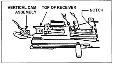
Figure 071-030-0001-22.
Engaging the vertical cam assembly.
|
(1)
Slide the vertical cam
assembly through the rear of the
receiver. The raised portion should
slide over the top of the receiver.
The drive lever lock should be
underneath.
|
(2)
Engage the forked end in
the notch.
|
i.
Engage the primary lever
(figure 071-030-0001-23).
|
|
Figure 071-030-0001-23.
Engaging the primary drive lever
|
(1)
Hold the vertical cam
assembly in place and slide the
primary drive lever into the receiver.
|
(2)
Slide the primary drive
lever lock to the rear and engage the
pivot post lever through the holes in
the receiver and vertical cam.
|
(3)
Slide the primary drive
lever lock forward. (The primary drive
lever lock is located on the vertical
cam just beneath the top of the
receiver).
|
j.
Insert the bolt and
backplate assembly (figure 071-030-0001-24).
|
|
Figure 071-030-0001-24.
Insertion of the bolt and backplate
assembly
|
(1)
Place the safe/fire switch
in the fire (F) position.
|
(2)
Press the receiver sear
using your thumbs or the rim of a
cartridge case.
|
(3)
Make sure the cocking lever
is cocked and forward.
|
(4)
Slide the bolt and
backplate assembly all the way
forward.
|
(5)
Insert the backplate pin to
lock the assembly in place.
|
(6)
Close the cover.
|
|
WARNING:
Before
inserting the bolt and backplate
assembly, put the cocking lever in
the forward position.
|
|
CAUTION:
Before closing
the top cover, always make sure the
secondary drive lever engages the
feed slide pin, the feed slide
assembly is to the left, and the
bolt is forward. Never try to force
the top cover closed. Doing so could
damage the weapon.
|
k.
Attach the receiver sear
assembly (figure 071-030-0001-25).
|
|
figure 071-030-0001-25. Attachment of the receiver sear
assembly
|
(1)
Turn the receiver over on
its top.
|
(2)
Place the sear housing on
the receiver and line up the sear
housing assembly at a right angle to
the barrel center line.
|
(3)
Put the safe/fire switch on
fire (F) position.
|
(4)
Press down and rotate the
housing assembly until it stops.
|
(5)
Press up on the sear and
rotate it until it locks in position.
|
l.
Attach the feed throat
assembly.
|
(1)
Squeeze the grip pins and
align them with the holes in the
receiver.
|
(2)
Release the grip pins to
attach the feed throat.
|
|
11. Perform a function check to make sure you have assembled the
weapon correctly.
|